
Publisher: Supplier of LED Display Time: 2017-12-02 13:39 Views: 2048
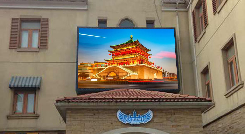
LED electronic display, it can play multimedia information such as videos, pictures, texts, tables, etc. Compared with traditional signage advertising, the brilliant graphics, text and video images of LED electronic display screens have more visual impact and are easier to attract people's attention. Moreover, the content of the broadcast is large and the content can be updated at any time. It has very good advertising. Effect. So what matters should be paid attention to during the installation and debugging of LED electronic display? The editor of LCF (www.lcf-led.com) summarizes the following points and hopes to be helpful to everyone.
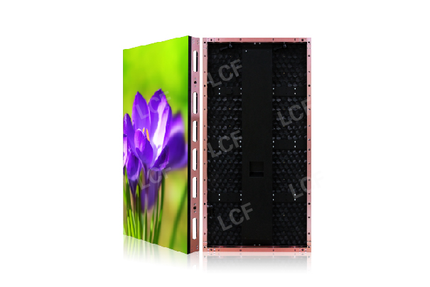
1. LED display frame size: the size of the frame is determined by the specifications of the finished product, but it is also subject to the specifications of the unit board. When cutting the material, pay attention to the width of the aluminum alloy frame. Subtract twice the width of the aluminum alloy frame from the finished product specifications, and the left and right vertical materials should also take care of this.
2. The corners are connected with plastic connectors, and finally fixed firmly with self-tapping screws. One corner shares four screws, one on each side and one on each side. After the frame is connected, the unit board can be placed.
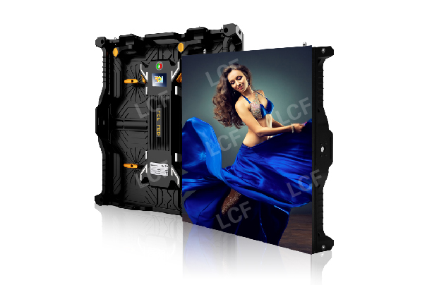
3. The placement of the unit board should be based on the specifications of the finished product. The size of 4.8*0.48 needs to be placed in horizontal 15 and vertical 3. Note that the placement of the unit board should be consistent with the direction of the arrow on the unit board.
4. Tighten the special screws to the unit board, and suck all the magnetic columns. The screws near the left and right sides of the frame should be screwed on the inner row of the unit board, so as to facilitate the fixing of the side back strips.
5. Install the back strip. The two ends of the back strip should be pre-punched with two holes at one end and a total of four holes on one. Use self-tapping screws to fix the frame material. Finally, let the magnetic column on the unit board be adsorbed on the back strip.
6. Connect the unit board with a data cable. One end of the data cable is inserted into the socket on the opposite right side of the left unit board, and the other end is connected to the socket on the left side of the adjacent unit board on the right across the back strip. Connect them one by one.
7. Connect the power cables between the unit boards. The red wire connects to the ACC terminal on the unit board, and the black wire connects to the GND terminal on the unit board. Connect them one by one, and be careful not to confuse them.
8. Install the power supply box and wiring. A 40A power supply box can be connected to a maximum of 12 unit boards on the Internet. Don't worry about consulting the boss and said that it is a maximum of 8 unit boards. Taking into account that if you bring too much, you will get hot, so I picked up by 8. Observe a total of 9 wiring terminals on the received power box. From left to right, they are: 1, 2 is the mains 220V interface, 3 is the ground wire, 4, 5, and 6 are all 5V positive stages, 7, 8, and 9 is the 5V negative pole. Just understand this and connect it yourself.
9. The number of wiring of the control card should correspond to the number of rows of the unit board, but pay attention to the color on the side of the data line (line) to be connected to the OE end on the control card, and the unit board also corresponds to it. The OE end cannot be reversed. The RS232 line is connected with the control card. In addition, the power supply on the control card should be connected to the 5V on the power box, corresponding to the positive and negative poles, and can not be connected to the 220V on the 1st and 2nd ends, otherwise the control card will be burned.
10. Connect the power cord. The power cord should be connected to the 1 and 2 ends of the power box. Don't confuse it. Make all the power boxes used in collusion. The other end leads to a two-hole plug for electricity use.


Shenzhen LCF Technology Co., Ltd.
Support Hotline
400-618-8884 / 0755-66833488(+86)187-0755-0636
Email:
shuaishuai1@lcf.technology
Company Address
LCF Sound & Optoelectronics Industry Park, Gushu, Bao'an District, Shenzhen.
Copyright © 2004-2024 LCF LED Display Screen All rights reserved. Guangdong ICP 15089785-3 Subsidiaries: Dongguan Tongdachuang Industrial Co., Ltd., Anshun Lianshunda Technology Co., Ltd. (holdings)